Garbage hardware and PCIe Bifurcation Part 3: Haswell
To start off, this post may contain images, methods, and hardware some may deem unnatural. Proceed at your own risk.
Haswell came out in what? 2013? Its older, slower, and lacks a great many modern features.
I'm of course, referring to the E3 Xeons, and their i$ whatever consumer counterparts. Socket 2011 and I are cool. Its processors have 40 lanes spread out.
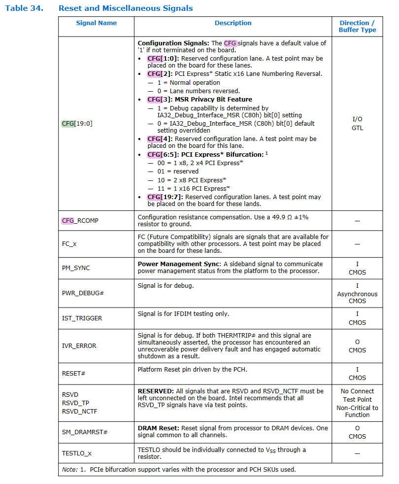
Looking at the silkscreen on motherboards, one sees an x16 slot, sadly populated by an x8 electrical slot. Sandy Bridge CAN split up PCIe slots so two x4 devices can be connected through a single (electrical) x8 slot. How do I know? The datasheet says so!
Specifically, table 34 of the succinctly named Desktop 4th Generation Intel® Core™ Processor Family, Desktop Intel® Pentium® Processor Family, and Desktop Intel® Celeron® Processor Family Datasheet – Volume 1 of 2

I assume Intel intended for the 2 x4 slots to be individual slots, rather than lumped together in one x8, but you play the hand you've got.
The challenge then is, how do you assert CFG[6] to Logic Low.
Based on experience with Sandy Bridge, I'm going to skip the whole BIOS editing and hidden options searching and go straight to the hardware modifications.
CFG[6] is the only one that needs to change (since our x16 slot is set to x8 per the motherboard manual, we can safely assume CFG[5] is already asserted to logic low).
So by going back to our trusty datasheet, we find CFG[6] is mapped to pin U40.

The next challenge is finding where, if anywhere, on the motherboard pin U40 goes to. Handily, that pin is on the far left, about halfway up the image. Its on the edge of the socket!
This would be trivial with a schematic, but none is available.
Since I'm still a very lazy man, I'm using this again.

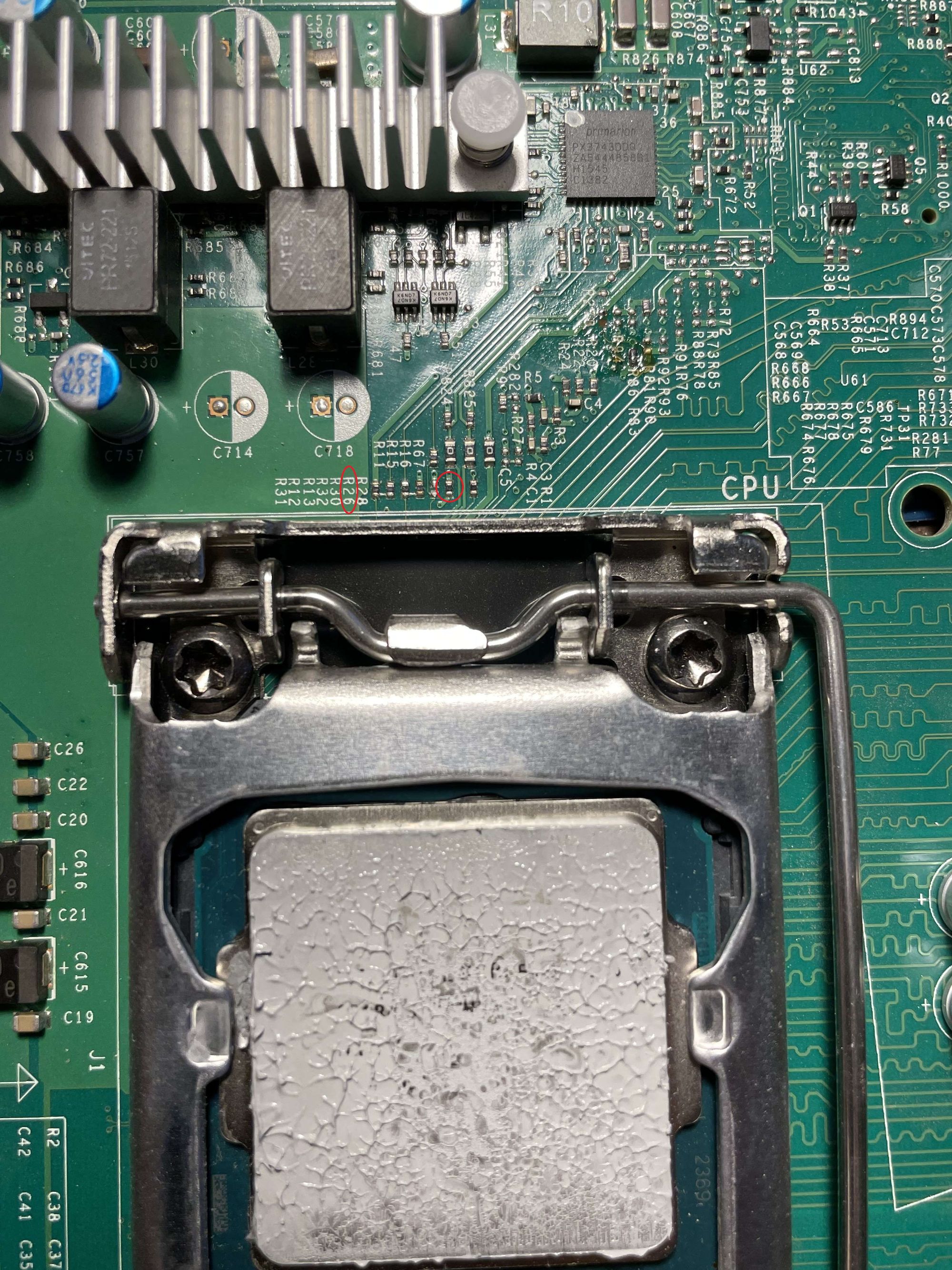
Supermicro X10SLH-F
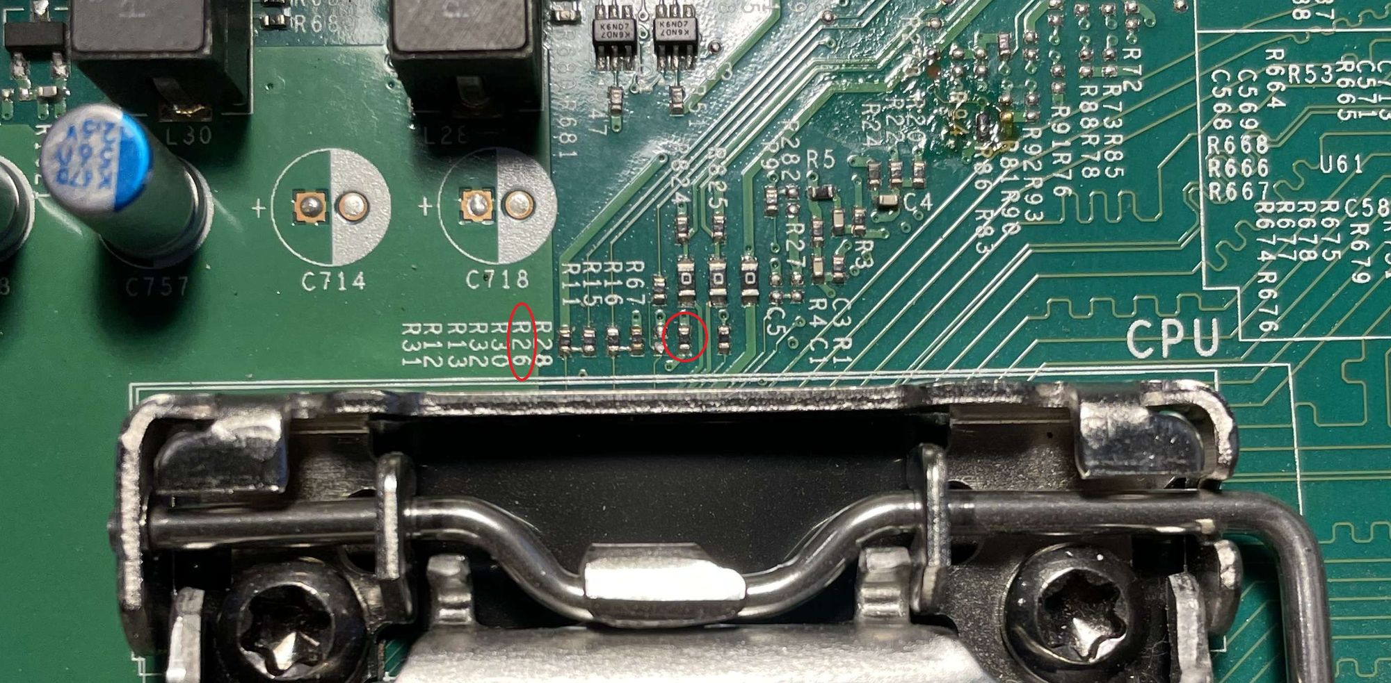
I find that U40 is connected to a blank resistor pad on the motherboard which we'll populate with a 0Ohm resistor. Probably should be 1k or something, but we'll trust Intel on this one. That should be the resistor marked R26 and is circled in RED


A quick reconnect and we find that the top slot (the x16 physical, x8 electrical) remains an x8, but the middle slot (x8 physical, x8 electrical) is now successfully bifurcated using the same dual nvme board described in earlier posts!
