Garbage hardware and PCIe Bifurcation Part 2: Sandy Bridge
To start off, this post may contain images, methods, and hardware some may deem unnatural. Proceed at your own risk.
Sandy Bridge came out in what? 2011? Its ancient, ugly, and lacks a great many modern features.
I'm of course, referring to the E3 Xeons, and their i$ whatever consumer counterparts. Socket 2011 and I are cool. Its processors have 40 lanes spread out.
Looking at the silkscreen on motherboards, one sees an x8 slot, sadly populated by an x4 device. Sandy Bridge CAN split up PCIe slots so two x4 devices can be connected through a single x8 slot. How do I know? The datasheet says so!
Specifically, table 6-5
I assume Intel intended for the 2 x4 slots to be individual slots, rather than lumped together in one x8, but you play the hand you've got.
The challenge then is, how do you assert CFG[6] to Logic Low.
Generally, processor options are set through one of three methods:
1) Hardware. Resistors and jumpers on the motherboard
2) Firmware. Microcode and smaller microprocessors coded and fused in the factory to say things like "You're an E3-1220V2".
3) BIOS. This code tends to control not just the processor, but smaller microprocessors onboard (like a southbridge, I/O controller, system memory)
We can't edit #2, well not easily.
#3 has a wide variety of tools available, so we'll start there.
We download the latest BIOS from Supermicro, and open it up with AMIBCP.
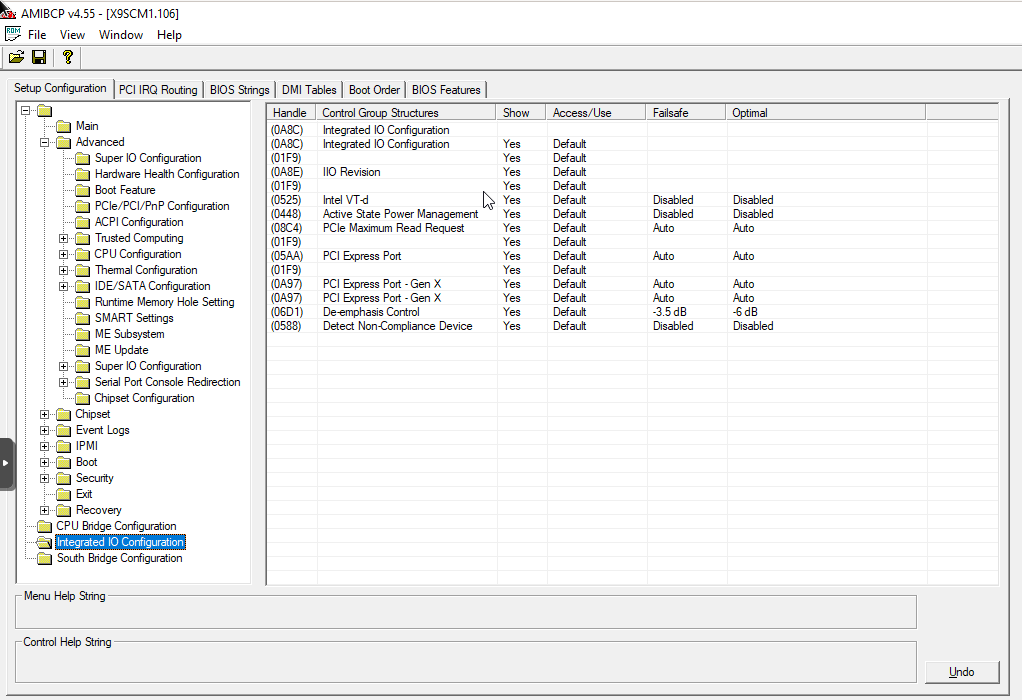
After going through the whole tree, we see everything is enabled and there are no hidden options. So we go to Option #1.
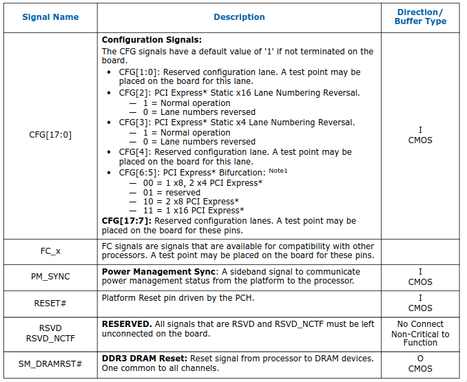
CFG[6] is the only one that needs to change (since we don't have an x16 slot anywhere, we can safely assume CFG[5] is already asserted to logic low).
So by going back to our trusty datasheet, we find CFG[6] is mapped to pin L37.
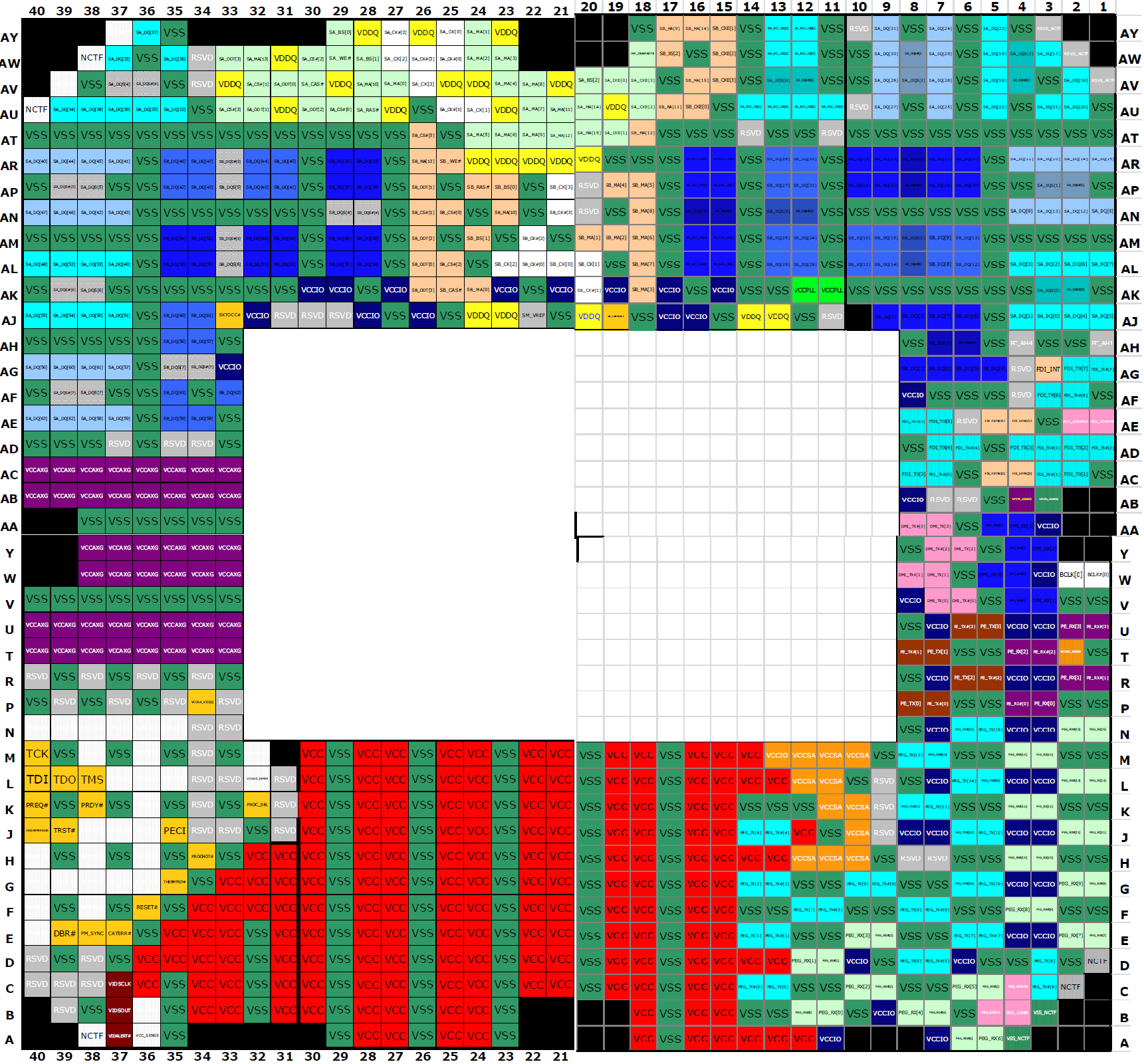
The next challenge is finding where, if anywhere, on the motherboard pin L37 goes to.
This would be trivial with a schematic, but none is available.
Since I'm a very lazy man, I came up with this:
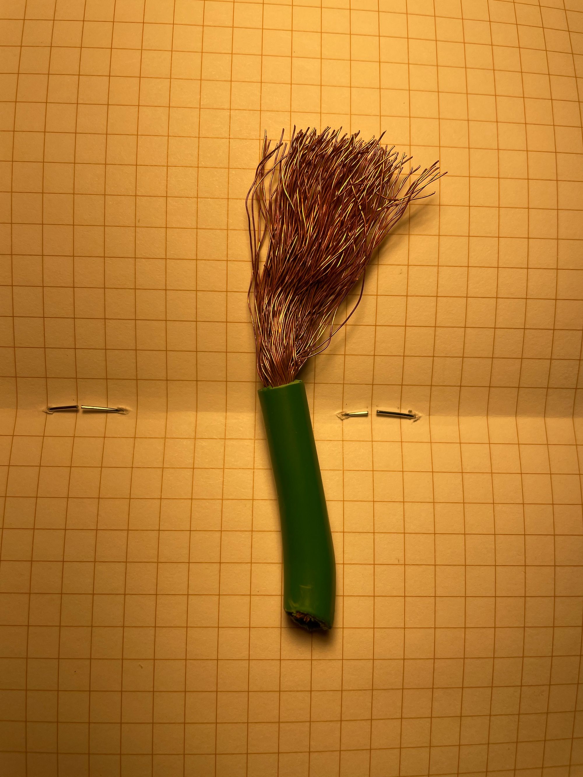
Stick one multimeter probe in the insulation, the other probe on the pin in question, and sweep the board (gently) until you hear the continuity beep. Then its much easier to hone in on the actual pin/pad in question.
I've got a few Sandy Bridge boards still in service, and as I get to documenting them, the specifics of how to perform this on them will be shown below.